
MOdeling services
TOOLS AND METHODS
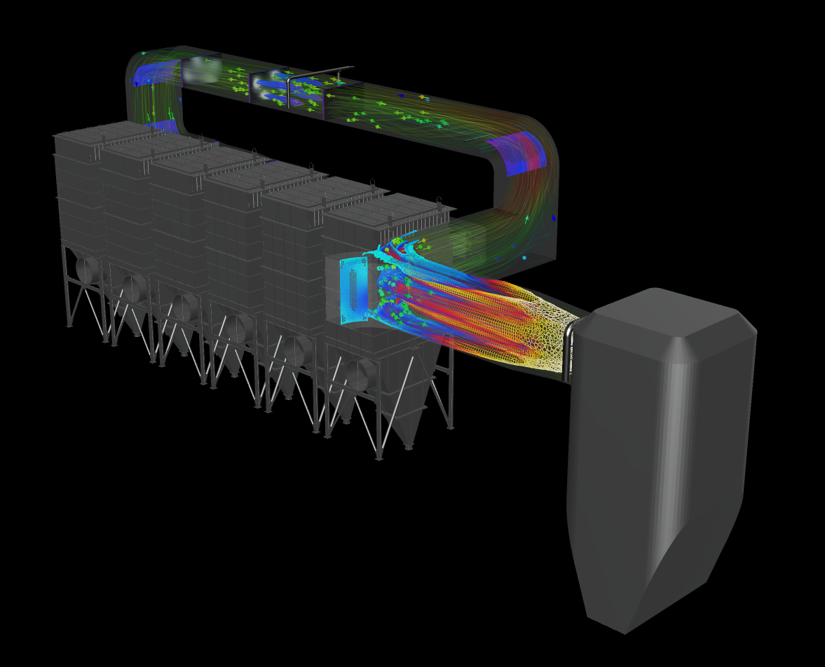
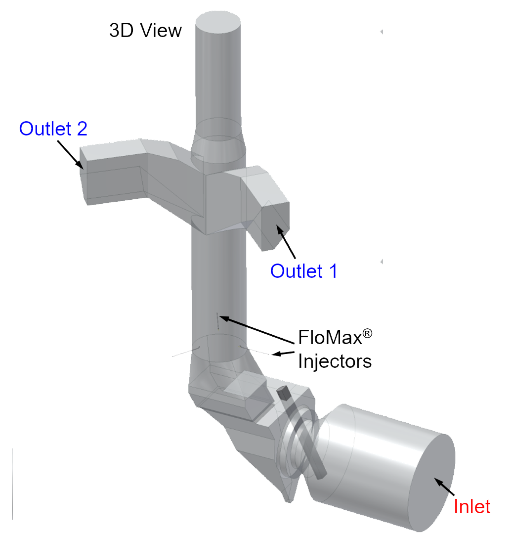
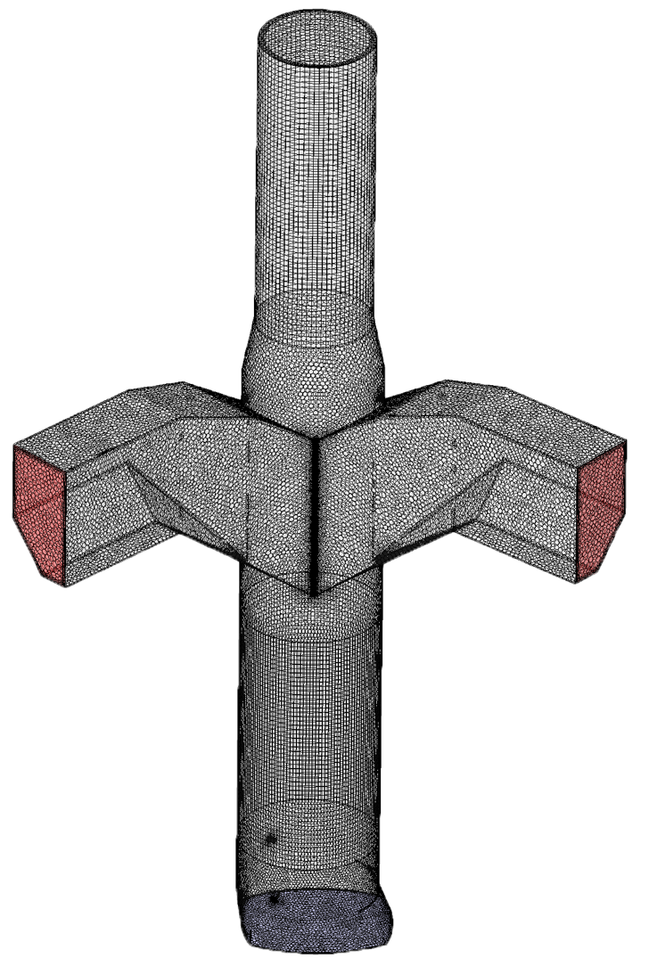
We use a combination of computational fluid dynamics (CFD), finite element analysis (FEA), and fluid structure interaction (FSI) to perform modeling simulations. Using our proprietary library of precision spray data, our research engineers simulate the behavior of fluids and sprays in complex geometries to solve your application issues and answer your application questions.
What is Computational Fluid Dynamics (CFD)?
THE BASICS
CFD, a branch of fluid mechanics, uses numerical analysis and data structures to analyze and solve fluid flow problems.
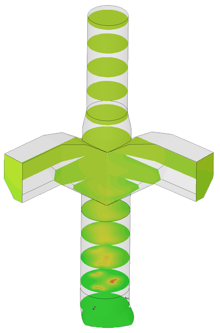
At its core, CFD is the science of predicting fluid flow, heat transfer, mass transfer, chemical reactions, and related phenomena by solving the mathematical equations governing these processes on a computer. Thus, CFD predicts how fluid and air will behave in a specific environment.
HOW ARE OUR SIMULATIONS DIFFERENT?
Our simulations are more accurate because we use a combination of highly specialized computer hardware, sophisticated programming and a proprietary library of precision data.
The specialized computer hardware and sophisticated programming is run by our experienced research engineers. Our proprietary data library comes from years of lab testing and has fine-tuned our algorithms/information on individual Spraying Systems Co. nozzles and systems.
What is Finite Element Analysis (FEA) and Fluid Structure Interaction (FSI)?
Finite Element Analysis (FEA)
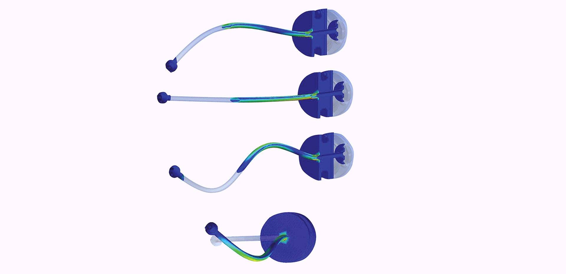
FEA is a numerical method (uses computational software) to predict how a part or assembly will perform under specific conditions. It is used as the basis for modern simulation software and helps engineers to find weak spots, areas of tension, etc., in their designs. The results of a simulation based on the FEA method are usually depicted via a color scale, similar to the above image. We use FEA as the basis for CFD and FSI simulations.
Fluid Structure Interaction (FSI)
FSI is the interaction of some movable or deformable structure with an internal or surrounding fluid flow. Fluid–structure interactions can be stable or oscillatory. In oscillatory interactions, the strain induced in the solid structure causes it to move such that the source of strain is reduced, and the structure returns to its former state only for the process to repeat.1 We use FSI, primarily, to assess the behavior of spray lances in various environments.
When Do We Use Modeling Simulations?
Solving spray problems, optimizing spray system performance and finding new ways to spray is our mission at Spray Analysis and Research Services.
In most cases, advanced or technical spray application questions are answered with testing in our state-of-the-art spray labs. If you want to discover, for example, how to better coat your customer's new biodegradable meat packaging with a food-safe mixture, we can test the exact operating conditions and find the nozzle system best suited to your customer's needs.
In some cases, however, testing in the labs is not possible.
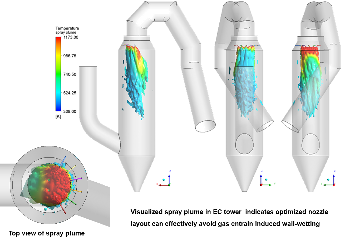
Perhaps your customer's nozzle resides in a chemical processing tower and so the environment is impossible to replicate in the lab. Maybe the spray material is hazardous and thus cannot be tested in the lab safely. Or, testing may be too costly or unrealistic because you need multiple variables tested. In these cases, our solution is to virtually simulate these applications using CFD.